


5.8GHz CW microwave sensor
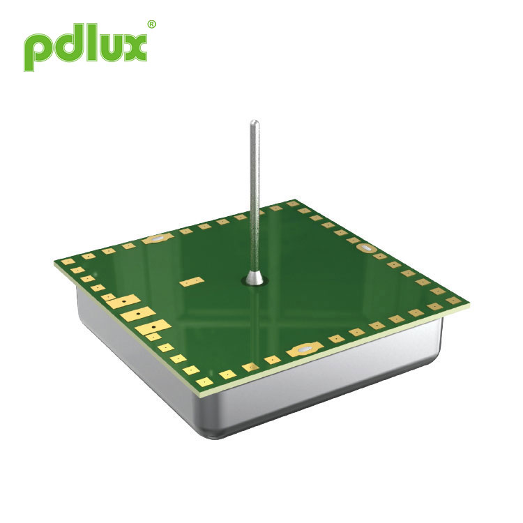
The 5.8GHz CW microwave sensor PD-MV1029A is a digital microwave sensing switch with a detection range of 360° and an operating frequency of 5.8GHz. The application of Doppler principle to transmit and receive signals, the control center uses MCU (micro control unit), accurately calculate the zero point of the power network sine wave, and switch at the zero point, improve the impact resistance, greatly reduce the failure rate.
Model:PD-MV1029A
Send Inquiry
Product Details
Summary
The 5.8GHz CW microwave sensor PD-MV1029A is a digital microwave sensing switch with a detection range of 360° and an operating frequency of 5.8GHz. The application of Doppler principle to transmit and receive signals, the control center uses MCU (micro control unit), accurately calculate the zero point of the power network sine wave, and switch at the zero point, improve the impact resistance, greatly reduce the failure rate. Exquisite appearance and compact structure, it can be connected to the load independently, or it can be used in a non-metallic housing, such as inside a lamp, and in other electrical products. It is widely used in passageways, toilets, elevators, homes or other public areas for safety protection or energy saving. It is the perfect choice for your smart life.
Specifications
| Power source | 100-240VAC,50Hz |
| Rated load |
1000W Max.(220-240VAC) 400W Max.(100-130VAC) |
| HF system | 5.8GHz(Center frequency)CW electric wave, ISM band |
| Detection range | 3-9m (radii.) (adjustable) |
| Time setting | 8sec-10min (adjustable) |
| Light-control | 10-300LUX~ daytime (adjustable) |
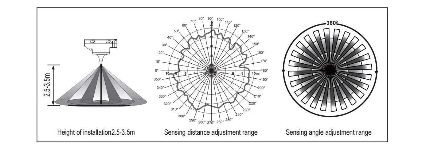
| Detection angle | 360° (ceiling installation) |
| Installation height | 2.5~3.5m |
| Standby power consumption | <0.5W |
| Working temperature | -15°C~+70°C |
| Working humidity | <95%RH |
| Senser motion speed | 0.6m/s -1.5m/s |
| Installation sit | indoors, ceiling mounting(wall mounted as required) IP20 |
Sensor Information
Function
Setting manner: potentiometerIt may take times to adjust values before they satisfy your need.
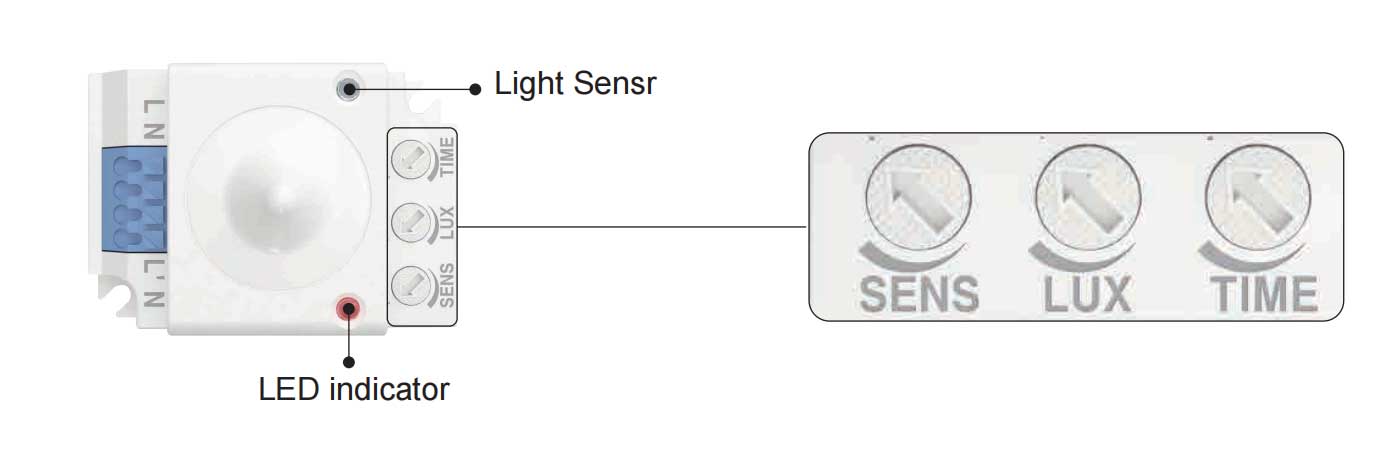
LED indicator:
(1) When you perform any adjustment of potentiometers, LED indicator lights on.
(2) When you perform any adjustment of potentiometers, 1 second after finishing adjustment LED indicator flashes twice and be off, then the system will memorize and auto-compute the exact function to the adjustment.
Pay attention!
Keep the potentiometer slow when turning, as the system will be constantly calculating according to the adjusted position, too fast may result in losing the optimal position!
-
(1)Detection range setting(sensitivity)
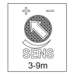
Detection range is the term used to describe the radii of the roughly circle casting on the ground when installed at the height of 2.5m. To turn fully anti-clockwise is the minimum distance, fully clockwise is the maximum. If person’s stature, figure and moving speed change, the detection will also change, that is, the higher speed will lead to the shorter detection distance.
Note: When the user is using, please adjust the sensitivity of the product to the appropriate position that needs to be used, and do not adjust the sensitivity of the product to the maximum, so as to avoid the misoperation caused by the wind blowing the curtains, trees, animals, power grids and electrical equipment caused by the ordinary start interference due to excessive sensitivity. When it is found that there are ordinary misactions in the use of the product, the user can try to reduce the sensitivity appropriately to test whether it is improved. -
(2)Light-control setting

The working illuminance value can be adjusted in the range of 10-300LUX~ daytime, which is set to control the induction environment light start-control threshold, counterclockwise rotation to the end, the working illuminance value is about 10LUX; Rotate clockwise to half, can be selected in the range of 10-300LUX; Continue to rotate to the end, the working illumination value is daytime (24 small is not affected by illumination). When testing or adjusting the detection area during the day, this knob must be turned clockwise to the end, and no matter how bright the ambient light is, the system is in a state of detection and induction.
-
(3)Time setting
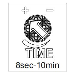
When the detected target moves, the sensing output will be triggered, and once the target stops moving, the system will automatically turn off the output according to the end of the set delay time (time setting: arrow pointing to "-" minimum is 8 seconds; arrow pointing to "+" maximum is 10 minutes). During the induction output process, the effective movement information is detected again in the effective detection area,and the set delay is refreshed. Wait 4 seconds after the system output is turned off before sensing again.
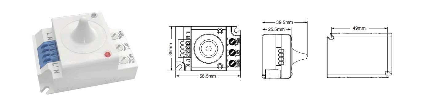
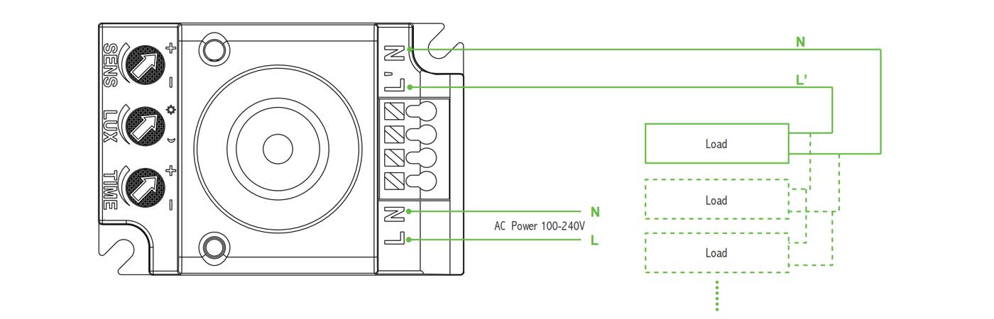
Connection-wire diagram
Connect N, L with power; Connect N, L’ with load.
Applications
Microwave can penetrate glass, plastic, ceramic and wood products, so it can be installed in a certain thickness of glass, plastic, ceramic and wood and other non-metallic surface. For example, applied in non-metal lamp shade lamp products, as long as you follow the correct wiring diagram connection, you can easily transform ordinary lamps into automatic induction lamps.
There are multiple options for actual use. You can also place one or more PD-MV1029A directly inside the ceiling or floor to control an aisle. Warm reminder: The installation distance between two or more products must be above 4 meters, otherwise it will cause mutual interference leading to misoperation.
| Fault | Failure cause | Solution |
| The load fails to work. | Light-illumination is set incorrectly | Adjust the setting of the load. |
| The load is broken. | Change the load. | |
| The power is off. | Turn the power on. | |
| The load works all the time. | There is a continuous signal in the region of the detection. | Check the settings of the detection area. |
| The load works when there is no motion signal detected. | The lamp isn't installed well so that sensor fails to detect reliable signals. | Re-adjust the installation place. |
| Moving signal is detected by the sensor (movement behind the wall, the movement of small objects, etc.) | Check the settings of the detection area. | |
| The load fails to work when there is motion signal detected. | The motion speed is too fast or the defined detection area is too small. | Check the settings of the detection area. |

The following situations will lead to error reaction.
1、Being installed on the rocking object will lead to error reaction.
2、The shaking curtain blown by wind will lead to error reaction. Please select the suitable place to install.
3、Being installed where the traffic is busy will lead to error reaction.
4、The sparks produced by some equipment nearby will lead to error reaction.
The following situations will lead to error reaction.
● Please confirm with prefessional installation.
● For safety purposes, please cut off power before installation and removal operations.
● Any losses caused by improper operation,the manufacturer does not undertake any responsibility.
This manual is for the current content programming of this product, there are any changes and modifications to the manufacturer without notice! It is strictly forbidden to copy the contents of the instruction manual for any other purpose without the permission of the company.