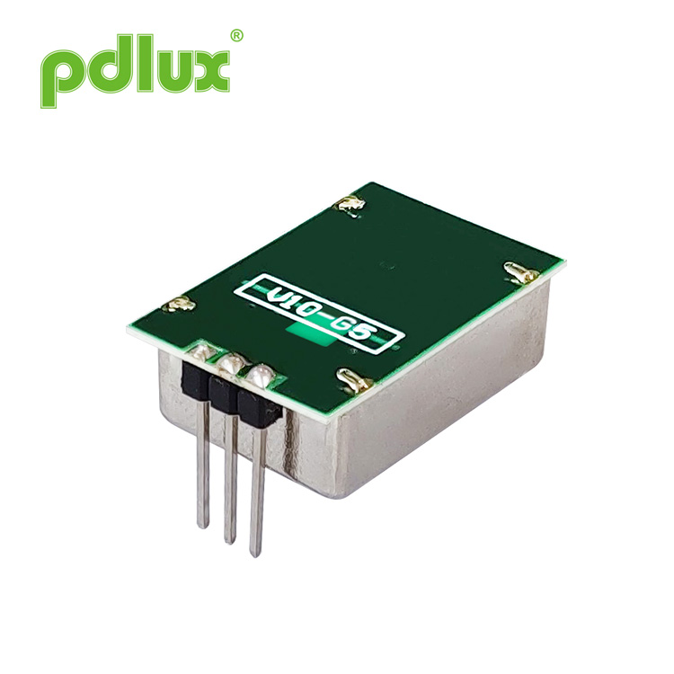
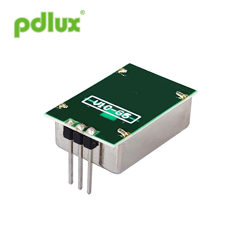
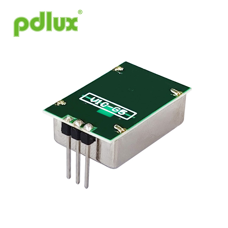
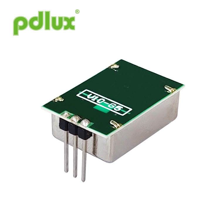
PDLUX PD-V9 Wall Installation 10.525GHz Microwave Sensor Module
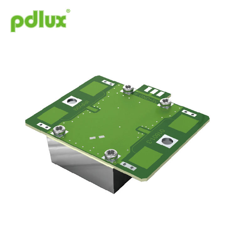
PDLUX PD-V9 Wall Installation 10.525GHz Microwave Sensor Module is a X-Band Bi-Static Doppler transceiver module .It’s built-in Resonator Oscillator (CRO).This module,V9 adopts flat Plane Antenna, suitable for wall mounting. Wall Installation 10.525GHz Microwave Sensor Module can improve its front signal receiving ability and reduce its flank blind area. Its performance is better than the sensors in the market.
Model:PDLUX PD-V9
Send Inquiry
Product Details
PDLUX PD-V9 Wall Installation 10.525GHz Microwave Sensor Module

PDLUX PD-V9 Wall Installation 10.525GHz Microwave Sensor Module is a X-Band Bi-Static Doppler transceiver module .It’s built-in Resonator Oscillator (CRO).This module,V9 adopts flat Plane Antenna, suitable for wall mounting. Wall Installation 10.525GHz Microwave Sensor Module can improve its front signal receiving ability and reduce its flank blind area. Its performance is better than the sensors in the market.
PDLUX PD-V9 Wall Installation 10.525GHz Microwave Sensor Module is ideally suitable for occupancy sensor in automatic lighting switches. Wall Installation 10.525GHz Microwave Sensor Module can also be used for ceiling mount intruder detectors.
|
Application of PDLUX PD-V9 Wall Installation 10.525GHz Microwave Sensor Module ●Intelligent switch ●Wall-hung switch ●Intruder detect Feature and advantage
●Low wireless power output |
According with EN 300440-V2.1.1、EN 62479:2010,RED directive-2014/53/eu
According with FCC Part 15.249 |
|
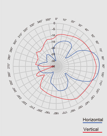
Antenna Beam Pattern
|
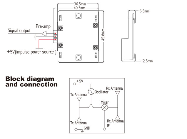
Size of PDLUX PD-V9 Wall Installation 10.525GHz Microwave Sensor Module
|
| Parameter | Notes | Min | Typ | Max | Units | ||||||
| Frequency Setting | 1 | 10.520 | 10.525 | 10.530 | GHz | ||||||
| Radiated Power (EIRP) | 1 | 2.0 | 2.5 | 3.0 | mW | ||||||
| Settling Time |
|
5 | 10 | 20 | μSec | ||||||
| Received Signal Strength | 2 | 150 | 200 | 250 | μVp-p | ||||||
| Noise | 3 | 4 | 4.5 | 5 | mVrms | ||||||
| Supply Voltage |
|
4.75 | 5.00 | 5.25 | V (impulse power source) | ||||||
| Current Consumption |
|
10 | 12 | 14 | mA | ||||||
| Pulse Repetition Frequency | 4 | 1.8 | 2.0 | 3.0 | KHz | ||||||
| Pulse Width | 4 | 10 | 20 | 30 | μSec | ||||||
| Operating Temperature |
|
-15 | 22 | 55 | ℃ | ||||||
| Weight |
|
7.5 | 8 | 8.5 | g | ||||||
Note1: The radiated emissions is designed to meet FCC rules.
Note2:The Received Signal Strength(RSS) is measured at the total 1 Ways path loss of 70dB.
Note3: The noise voltages are measured from 10Hz to 100Hz at the Output port, inside an Anechoic chamber.
Note4: Pulse operation


