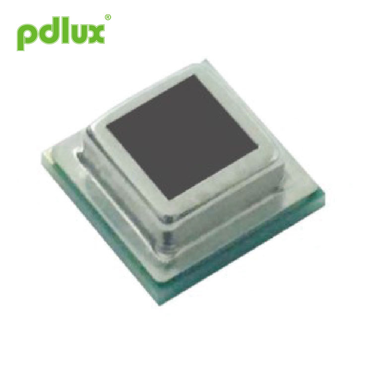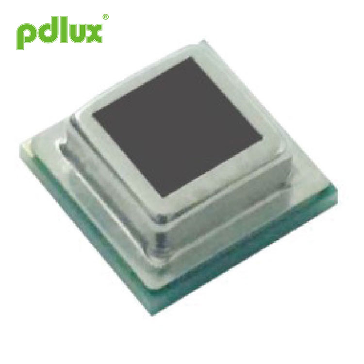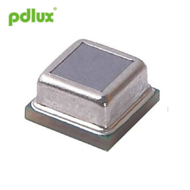


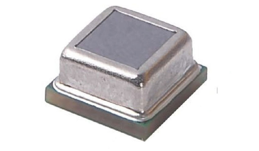
MINI SMD Four Element Anti Jamming Digital Pyroelectric Infrared Sensor
When the pyroelectric infrared signal received by the MINI SMD Four Element Anti Jamming Digital Pyroelectric Infrared Sensor exceeds the trigger threshold inside the probe, a counting pulse is generated internally. When the probe receives such a signal again, it will think that it has received the second pulse. Once it receives 2 pulses within 4 seconds, the probe will generate an alarm signal and the REL pin will have a high level trigger.
Model:PD-PIR-462LA-D
Send Inquiry
Product Details
MINI SMD Four Element Anti Jamming Digital Pyroelectric Infrared Sensor
|
Features Small SMD reflow soldering method Digital signal processing Enable power regulation to save energy Built-in filter, strong anti-interference Adjustable sensitivity, timing and light control Low voltage, micro power consumption |
Application Infrared movement detection Internet of Things Wearables Smart home appliances, home Smart luminaires Security, automotive anti-theft products Network monitoring system, etc |
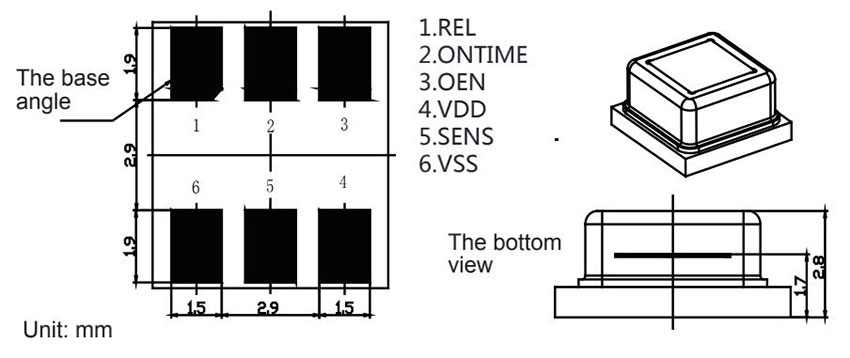
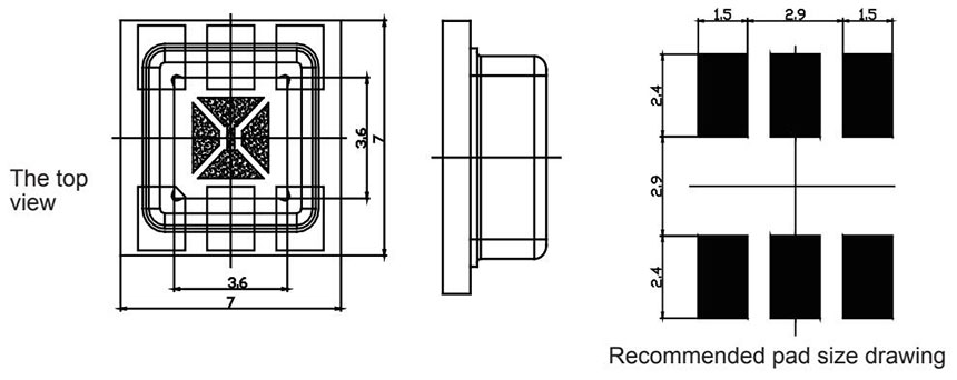
Product and recommended pad size diagram of MINI SMD Four Element Anti Jamming Digital Pyroelectric Infrared Sensor
Basic parameters of MINI SMD Four Element Anti Jamming Digital Pyroelectric Infrared Sensor
Anything beyond the ratings in the following table may cause permanent damage to the device. Long-term use near the rated value may affect the reliability of the device.
|
Parameters |
Symbol |
Min |
Max |
Unit |
Note |
|
Voltage |
VDD |
2.2 |
3.7 |
V |
|
|
View angle |
|
X=110° |
Y=90° |
° |
The field of view angle is a theoretical value |
|
Storage temperature |
TST |
-40 |
80 |
℃ |
|
|
Detect wavelengths |
λ |
5 |
14 |
μm |
|
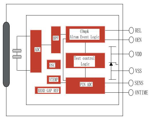
Internal block diagram
Working conditions (T=25° C, VDD=3V, unless otherwise specified)
|
Parameters |
Symbol |
Min |
Typ |
Max |
Unit |
Note |
|
Supply Voltage |
VDD |
2.2 |
3 |
3.7 |
V |
|
|
Working current |
IDD |
9 |
9.5 |
11 |
μA |
|
|
Sensitivity threshold |
VSENS |
90 |
|
2000 |
μV |
|
|
Output REL |
||||||
|
Low output current |
IOL |
10 |
|
|
mA |
VOL<1V |
|
Output high current |
IOH |
|
|
-10 |
mA |
VOH>(VDD-1V) |
|
REL low level output lock time |
TOL |
|
2 |
|
s |
Not adjustable |
|
REL high level output lock time |
TOH |
2 |
|
3600 |
s |
|
|
Enter SENS/ONTIME |
||||||
|
Voltage input range |
|
0 |
|
VDD/2 |
V |
The adjustment range is between 0V and VDD/2 |
|
Input bias current |
|
-1 |
|
1 |
μA |
|
|
Enable OEN |
||||||
|
Input low voltage |
VIL |
Between 0.8V-1.2V is the hysteresis area |
0.8 |
V |
OEN voltage high to low threshold level |
|
|
Input high voltage |
VIH |
1.2 |
|
|
V |
OEN voltage low to high threshold level |
|
Enter the current |
II |
-1 |
|
1 |
μA |
Vss<VIN<VDD |
|
Oscillators and filters |
|
|
|
|
|
|
|
Low-pass filter cutoff frequency |
|
|
|
7 |
Hz |
|
|
High-pass filter cut-off frequency |
|
|
|
0.44 |
Hz |
|
|
The oscillator frequency on the chip |
FCLK |
|
|
64 |
kHz |
|
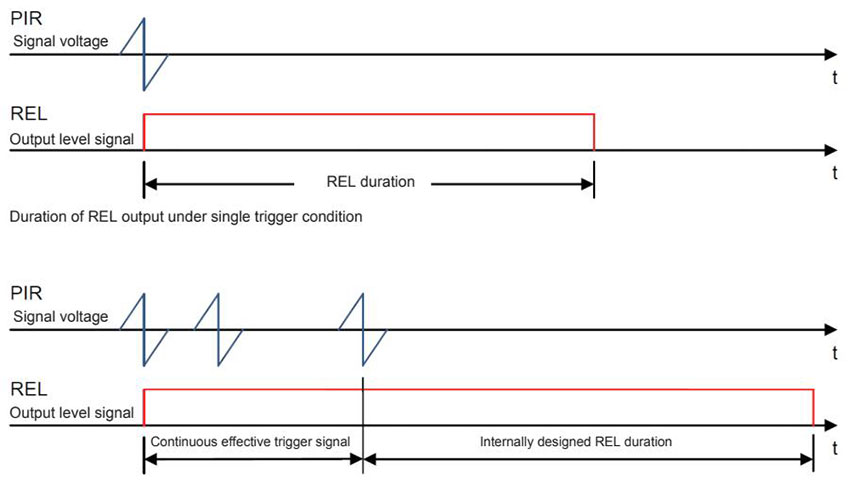
Output trigger mode
When the pyroelectric infrared signal received by the probe exceeds the trigger threshold inside the probe, a counting pulse is generated internally. When the probe receives such a signal again, it will think that it has received the second pulse. Once it receives 2 pulses within 4 seconds, the probe will generate an alarm signal and the REL pin will have a high level trigger.In addition, as long as the received signal amplitude exceeds more than 5 times the trigger threshold, only one pulse is required to trigger the output of the REL.The following figure is an example of trigger logic diagram. In the case of multiple triggers, the maintenance time of output REL starts from the last valid pulse.
ONTIME pin timing setting
When the probe detects the human body movement signal, it will output a high level on the REL pin. The duration of this level is determined by the level applied to the ONTIME pin (see the table below). If the REL high level device has multiple trigger signals generated, as long as a new trigger signal is detected, the REL time will be reset, and then the timing will be restarted.
1. The working current is related to the selected resistance R. The larger the resistance, the smaller the working current. The average current consumed by R during the REL effective delay period is: IR ≈ 0.75VDD/R. During the ineffective delay period, R consumes no current. If you have high power consumption requirements and are often in the effective delay time period, it is recommended to use the digital REL timing mode.
2. If the digital REL timing mode is adopted, the ONTIME pin is connected to a fixed potential whose maximum value is less than VDD/2 (in actual use, the resistor divider can be used to adjust the REL timing). The ONTIME input voltage sets the REL output holding time through the only trigger. Refer to the table below for the output delay timing (Time Td) and voltage settings. Note: When using the digital REL timing method, the ONTIME pin voltage must not be higher than VDD/2, and the timing time can only be selected from one of the 16 times in the table below. If the time in the table below is not suitable, it is recommended to use the analog REL timing method.
|
Time gear |
Setting time (s) (Typical value) |
TIME pin voltage range |
Typ |
Recommended value of divider resistor (accuracy ±1%) |
|
|
|
|
|
|
Pull-up resistor RH |
Pull-down resistance RL |
|
1 |
2 |
0~1/32VDD |
1/64VDD |
Not posted/1M |
0R |
|
2 |
5 |
1/32VDD~2/32VDD |
3/64VDD |
1M |
51K |
|
3 |
10 |
2/32VDD~3/32VDD |
5/64VDD |
1M |
82K |
|
4 |
15 |
3/32VDD~4/32VDD |
7/64VDD |
1M |
124K |
|
5 |
20 |
4/32VDD~5/32VDD |
9/64VDD |
1M |
165K |
|
6 |
30 |
5/32VDD~6/32VDD |
11/64VDD |
1M |
210K |
|
7 |
45 |
6/32VDD~7/32VDD |
13/64VDD |
1M |
255K |
|
8 |
60 |
7/32VDD~8/32VDD |
15/64VDD |
1M |
309K |
|
9 |
90 |
8/32VDD~9/32VDD |
17/64VDD |
1M |
360K |
|
10 |
120 |
9/32VDD~10/32VDD |
19/64VDD |
1M |
422K |
|
11 |
180 |
10/32VDD~11/32VDD |
21/64VDD |
1M |
487K |
|
12 |
300 |
11/32VDD~12/32VDD |
23/64VDD |
1M |
560K |
|
13 |
600 |
12/32VDD~13/32VDD |
25/64VDD |
1M |
634K |
|
14 |
900 |
13/32VDD~14/32VDD |
27/64VDD |
1M |
732K |
|
15 |
1800 |
14/32VDD~16/32VDD |
29/64VDD |
1M |
825K |
|
16 |
3600 |
15/32VDD~16/32VDD |
31/64VDD |
1M |
953K |
Sensitivity settings
|
NO. |
SENS pin voltage |
NO. |
SENS pin voltage |
||
|
|
Voltage range (VDD) |
Central voltage (VDD) |
|
Voltage range (VDD) |
Central voltage (VDD) |
|
0 |
0~1/64 |
1/128 |
16 |
16/64~17/64 |
33/128 |
|
1 |
1/64~2/64 |
3/128 |
17 |
17/64~18/64 |
35/128 |
|
2 |
2/64~3/64 |
5/128 |
18 |
18/64~19/64 |
37/128 |
|
3 |
3/64~4/64 |
7/128 |
19 |
19/64~20/64 |
39/128 |
|
4 |
4/64~5/64 |
9/128 |
20 |
20/64~21/64 |
41/128 |
|
5 |
5/64~6/64 |
11/128 |
21 |
21/64~22/64 |
43/128 |
|
6 |
6/64~7/64 |
13/128 |
22 |
22/64~23/64 |
45/128 |
|
7 |
7/64~8/64 |
15/128 |
23 |
23/64~24/64 |
47/128 |
|
8 |
8/64~9/64 |
17/128 |
24 |
24/64~25/64 |
49/128 |
|
9 |
9/64~10/64 |
19/128 |
25 |
25/64~26/64 |
51/128 |
|
10 |
10/64~11/64 |
21/128 |
26 |
26/64~27/64 |
53/128 |
|
11 |
11/64~12/64 |
23/128 |
27 |
27/64~28/64 |
55/128 |
|
12 |
12/64~13/64 |
25/128 |
28 |
28/64~29/64 |
57/128 |
|
13 |
13/64~14/64 |
27/128 |
29 |
29/64~30/64 |
59/128 |
|
14 |
14/64~15/64 |
29/128 |
30 |
30/64~31/64 |
61/128 |
|
15 |
15/64~16/64 |
31/128 |
31 |
31/64~32/64 |
63/128 |
The voltage input by SENS sets the sensitivity threshold, which is used to detect the strength of the PIR signal input by PIRIN and NPIRIN. When grounded, it is the minimum voltage threshold, and the sensitivity is the highest at this time. Any voltage exceeding VDD/2 will select the maximum threshold. This threshold is the lowest sensitive setting for PIR signal detection, that is, the sensing distance may be the smallest. It should be pointed out that the sensing distance of the infrared sensor is not linearly related to the SENS input voltage. Its distance is related to the signal-to-noise ratio of the sensor itself, the imaging object distance of the Fresnel lens, the background temperature of the moving human body, the ambient temperature, the ambient humidity, and electromagnetic interference. And other factors form a complex and multiple relationship, that is, the output result cannot be judged by a single index, and the debugging result shall prevail in actual use. The lower the voltage of the SENS pin, the higher the sensitivity, and the longer the sensing distance. There are a total of 32 sensing distances to choose from, and the closest sensing distance can reach centimeter level. In actual use, the resistance divider can be used to adjust the sensitivity.
OEN pin settings
OEN is the enable pin for REL output. When OEN inputs a low voltage, the REL output is always low; when OEN inputs a high voltage, when the PININ /NPIRIN pin senses a normal human body trigger signal through the sensor, REL outputs a high level until there is no human body trigger signal, and it passes REL After the timing time, REL outputs low level. After a shielding time of about 2 seconds, the human body signal can be sensed again. OEN pin can be connected to photoresistor or photodiode to realize the function of not working during the day and working at night.
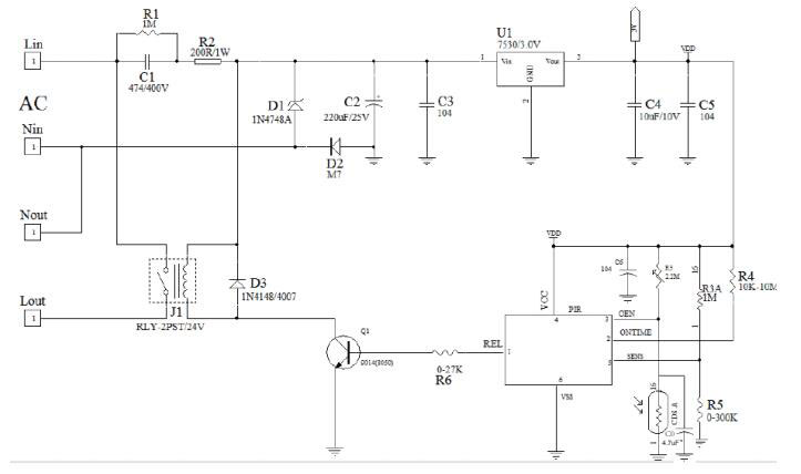
Typical application circuit
Triode application example
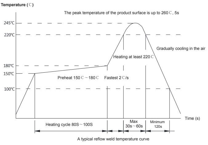
Reflow soldering
Sensor reflow soldering instructions
When reflow soldering, please follow the temperature curve shown in the figure below. Anything that exceeds the reflow temperature shown in the figure below must consult the sales engineer in advance.
Packaging
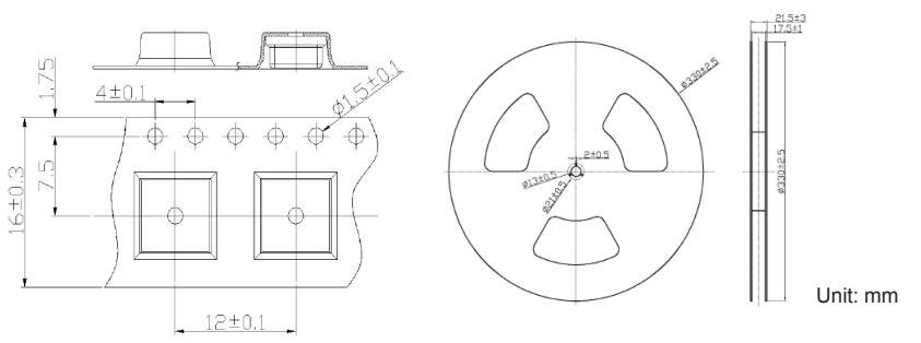
Note: The standard package is 1000 pieces, and the package quantity and size vary slightly according to different models.
Note for welding
Do not exceed the maximum temperature of the temperature curve shown in the figure above, otherwise it may cause the sensor performance degradation.
Do not repeat reflow soldering and repeated heating and disassembly, which will seriously affect the life and performance of the sensor and is not covered by the product warranty.
Do not use corrosive chemicals to clean the optical filter (absolute ethanol can be used), which may cause the sensor to malfunction or fail. Do not use it immediately after the sensor is mounted, it is recommended to use it after 1H.
Be careful not to touch the terminals with metal pieces or hands. Note for welding:
Operating environment temperature (humidity) range
> Temperature: Working temperature: -30℃~+70℃ (no fog or icing, temperature change may cause sensitivity and distance change) Storage temperature: -40℃~ +80℃
> Humidity: Working humidity: ≤ 85%RH (should not be fogged or frozen)
Storage humidity: ≤ 60%RH
> Regarding the use environment temperature and the scope of adaptation, it refers to the temperature and humidity that can make the sensor work continuously, not the continuous work guarantee for durability and environmental resistance. When used in a high temperature and high humidity environment, the sensor will accelerate aging.
Other considerations
> Misoperation may occur due to electrothermal noise such as static electricity, lightning, mobile phones, radios, and high-intensity light.
> The customer terminal product should be installed firmly to avoid malfunction caused by wind and shaking.
> It will be damaged after strong vibration or impact and cause malfunction. Please avoid high-strength vibration or impact.
> This product is not a waterproof and dustproof product. It should be waterproof, dustproof, anti-condensation and anti-icing when using it.
> If corrosive gas volatilizes in the working environment, it will cause malfunction.