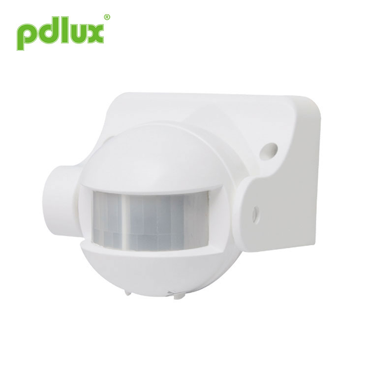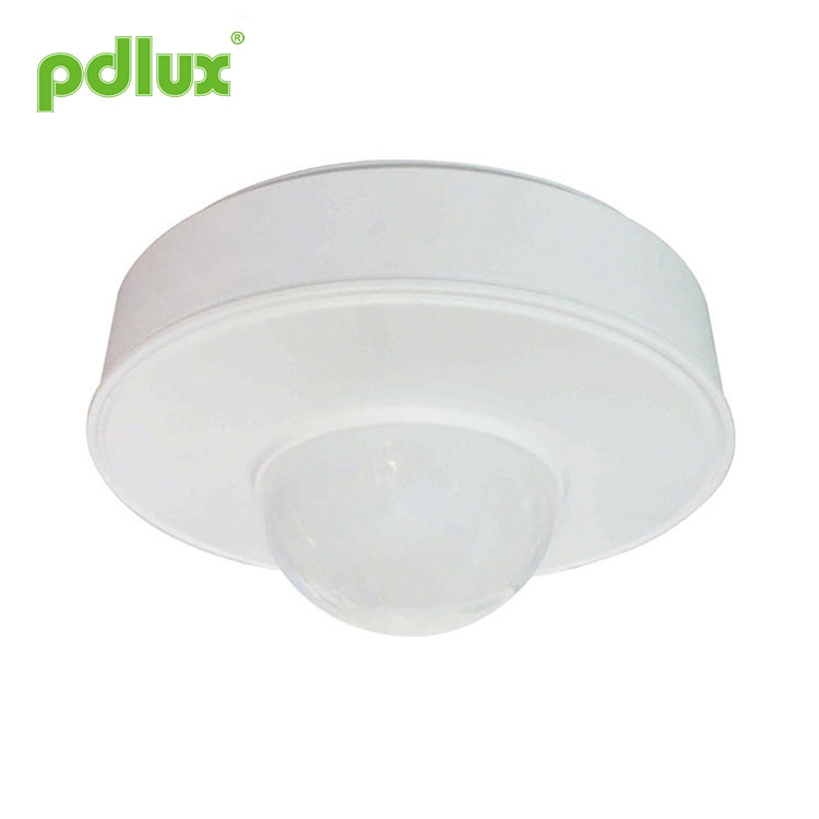


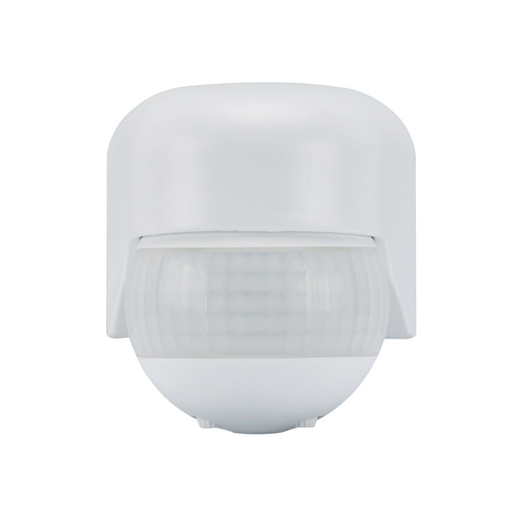
PIR Movement Sensor Detector Switch
The following is an introduction to PIR Movement Sensor Detector Switch, I hope to help you better understand PIR Movement Sensor Detector Switch.
Model:PD-PIR155
Send Inquiry
Product Details
PD-PIR155 Infrared Sensor Instruction
IP 65
Summary
This PIR Movement Sensor Detector Switch is an advanced digitally controlled infrared pyroelectric intelligent sensor product.It uses the MCU to accurately calculate the switch information, and accurately controls the relay to be turned on at the zero point of the sine wave, so that each load is turned on. At the zero point of the sine wave, the inrush current problem caused by the conventional control mode when the sine wave high voltage is turned on is avoided, especially the large current damage relay generated by the large-capacity capacitor under the impact of the high voltage under the load.Due to the diversification of current electrical loads, especially LED lamps, energy-saving lamps, and fluorescent lamps all have capacitors with different capacitances. This is a disaster for relays. Sometimes a 50W LED lamp can generate surge currents of 80 to 120A. The 10A ordinary relay can only withstand 3 times of the inrush current, and it is likely that the relay will be broken in a few days or several times. This is why the conventional sensor on the market has a short life and a small load current.
In order to overcome this problem, this product adopts advanced digital precision calculation to turn on the load when the sine wave is at zero potential, thus solving the load surge current problem, greatly enhancing the load capacity and prolonging the service life of the product. The latest control method of mass production sensor technology can easily control any load. It is a medium and high-end product. Although the cost is increased compared with the conventional version, the reliability and life of the product are greatly increased. This product is equal to choosing peace of mind, and choosing safety.
This product has a switching power supply version and a capacitor step-down version. The switching power supply version has a working voltage of up to 100V-277V and a standby power consumption of <0.5W. In principle, the capacitive step-down version can only have a single voltage, and the standby power consumption is >0.7W. You should consider it when choosing a product.
Specifications
|
Power source: 220-240VAC,50Hz/60Hz 100-130VAC,50Hz/60Hz All loads:1200W Max.(220-240VAC ) 800W Max.(100-130VAC) Time setting: 12sec-12min(adjustable) Light-control: <10LUX-2000LUX(adjustable) |
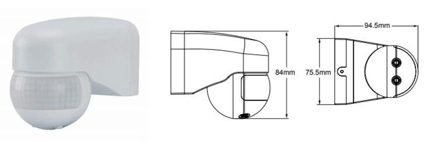
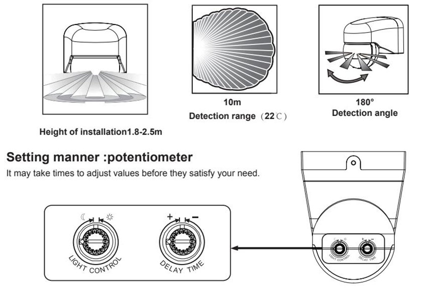
Detection range(22°C): 10m Max. Detection angle: 180º Installation height: 1.8-2.5m Working temperature: -10°C-+40°C Working humidity: <93%RH Sense motion speed: 0.6-1.5m/s |
Function
LUX adjustment:
LUX refers to the illuminance of the environment. Adjusting the LUX adjustment knob allows you to choose which illuminance you want to get the sensor into the induction. Choose the habit that suits you.
Some of the choices in the 20LUX solution are to be illuminated. Some choose 50LUX ambient illumination to be inductive lighting, and some choose to be inductive lighting at any time, as long as the LUX adjustment knob is adjusted to the maximum.
Time adjustment:
The time adjustment knob is used to adjust the time after the sensor senses the light, and the user can reasonably select the delay time after the induction.
Sensor information
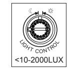 |
(1)Light-control setting It can be defined in the range of <10~2000 LUX. To turn the knob fully clockwise is about 10 lux,fully anti-clockwise is about 2000 lux.When adjusting the detection zone and performing the walk test in daylight,you should turn the knob fully clockwise. |
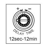 |
(2)Time setting It can be defined from 12 seconds(turn fully anti-clockwise) to 12minutes(turn fully clockwise). Any movement detected before this time elapses will re-start the timer. It is recommended to select the shortest time for adjusting the detection range and for performing the walk test. |
NOTE:When the light be auto off,it will take 1 second before the sensor is ready to detect another movement,that is,only signal detected 1 seconds later can the light be auto-on.
It is mainly for the adjustment of the delay time from the moment the signal detected and light auto-on till the light auto-off. You can define the delay time to your practical need. But you’d better lower the delay time for the sake of energy saving, since the microwave sensor has the function of continuous sensing, that is, any movement detected before the delay time elapses will re-start the timer and the light will keep on only if there is human in the detection range.
|
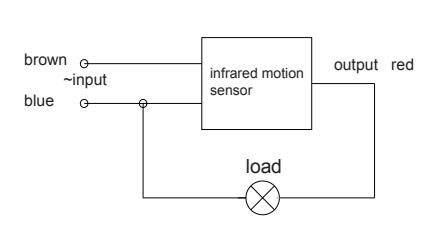
Connection -wire diagram I. Connect line according to the right figure. N – blueL – brown L’ – red ( be from infrared sensor) connect blue and brown with power connect blue and red with load. |
 |
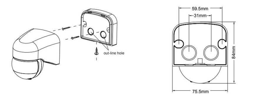
Installation
1、Switch off the power;
2、Screw off the nail on the bottom. Open the wire hole. The power wire and the load wire are bored in the bottom;
3、The bottom is fixed on the selected position with the inflated screw;
4、Connect the power and the load with the connection-wire column according to the sketch diagram;
5、The sensor is fixed on the bottom, please screw the nail and connect the power. Then you can test it.
|
Test 1. After installation, pleaseturn the light-control knob(1) anti-clockwise to the maximum value. turn anti-clockwise the time knob(2) to the end before you switch on the power. 2.The power connection, the load will start working, 30 seconds often after the normal induction mode. 3. Once detected, the load works and the indicator on and stops working 12 seconds later when there is no continual signal detected.And if signal detected 3 seconds later, the load should start working and the indicator on and stop working 12 seconds later when there is no continual signal detected. 4. Turns LUX knob anti-clockwise to the minimum. If it is tested under the circumstance above 10LUX, load should not work after induction load stop working; but if you cover the detection window with opaque objects (towel etc), the load works. Under the condition of no induction signals, the load should stop working within 12 sec. |
 |
Notes
Electrician or experienced human can install it.
The unrest objects can’t be regarded the installation basis-face.
In front of the detection window there should be no hinder or unrest objects effecting detection.
Avoid installing it near air temperature alteration zones for example: air condition, central heating, etc.
Please don’t open the case for your safety if you find the hitch after installation.
Remark
1. Keep the sensor face to the area where human usually move.
2. Keep the sensor face to the position of the ambient light in order to get much more exact illuminance setting.
3. If detect the signal again within the time-delay, the time-delay will be over lied.
4. LUX knob: the luminance of working conditions .When the knob switches “+” , it means it can detect all day,when the knob switches “ - ” , it will only work below the luminance <10 LUX.
5. TIME knob:It is a period that the light turns on slowly to no any signal gradually, till out of work.
Some problem and solved way
The load don’t work:
a: Check the power and the load.
b: If the load is good.
c: Please check if the working light correspond to the ambient light.
The sensitivity is poor:
a: Please check if in front of the detection window there is hinder that effect to receive the signals.
b: Please check if the ambient temperature is too high.
c: Please check if the signals source is in the detection fields.
d: If the moving orientation is right.
The sensor can’t shut automatically the load:
a: If there is continual signal in the detection fields.
b: If the time delay is set to the longest.
c: If the power correspond to the instruction.
d: If the air temperature change near the sensor, for example air condition or central heating etc.

● Please confirm with prefessional installation.
● Please cut off power supply before installation and removal operations.
● Make sure that you have cut off the power for safety purposes.
● Improper operation caused losses, the manufacturer does not undertake any responsibility.
This manual is for the current content programming of this product, there are any changes and modifications to the manufacturer without notice!
This instruction, without our permission, should not be copied for any other purposes.
Hot Tags: PIR Movement Sensor Detector Switch, China, Manufacturers, Suppliers, Factory, Wholesale, Customized
Related Category
Send Inquiry
Please Feel free to give your inquiry in the form below. We will reply you in 24 hours.